Please Choose Your Language
close
Choose Your Site
Global
Social Media


| Quantity: | |
|---|---|
| PDF Export | |


M212E
SiRON
8503009090
About selection
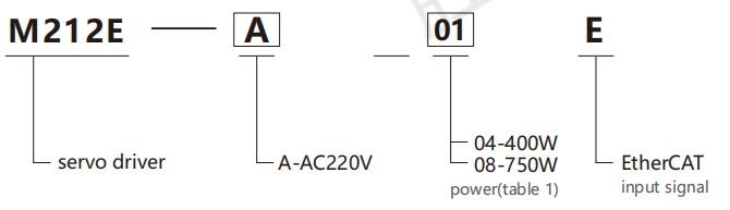
Selection example: M212E-A01E represents the M212E series servo driver, with a power supply voltage of AC220V, a power of 100W, and an input signal of EtherCAT.
Note: 1. Power supply voltage AC220V: The power selectable range is 100 to 1000W. The M212E series servo driver can be matched with the M202 series servo motor.
Table 1: Power
| Voltage | AC 220V | |||||
| Code | 01 | 02 | 04 | 06 | 08 | 10 |
| Power | 100W | 200w | 400W | 600W | 750W | 1000W |
Specification
| Name | M212E series servo drive | |
| Input Power | Single-phase AC220V | |
| Control Mode | Position pulse mode,internal register position modeanalog speed mode, internal register speed mode,analog torque mode,internal register torque mode,hybrid control mode,etc | |
| Controlcharacteristics | Motortype | permanent magnet synchronous motor |
| Speed Response Frequency | 1.2KHz | |
| Velocity Volatility | 0.01%(load 0~100%) | |
| Speed bump | 0.01%(load 0~100%) | |
| Speed ratio | 1:10000 | |
Inputpulse frequency | 1、500KHz(differential)200KHz(open collector) 2、The receiving frequency of the high-speed pulse circuit is 4MHZ(differential type). | |
| Input Signal | Control input | Servo enable,alam reset,command pulse clearance,command pulse prohibition,forward rota tion prohibition,forward rotation torque limit,reverse rotation torque limit,internal speed sele ction,internal position trigger,origin retrieval trigger,zero speed clamping.etc |
| Output signal | Control output | Servo ready,servo alarm,position arrival,speed arrival,battery brake output,rotation detectio n,speed limit in the middle,origin location,torque limit in the middle |
| Encodersignal split frequency output | Three output methods:1.Open-circuit output of the collector of phase Z of the encoder2.The encoder's A and B phase frequency division signals are differentially output(without isolation) for arbitrary frequency division3.Z-pulse time expansion function | |
| Position contral | Inputmethod | Two phase orthogonal pulse,forward rotation pulse +reverse rotation pulse,pulse +diretio- n,internal register |
| Electronicgearratios | 1、0.01≤B/A≤100002.It supports two sets ofelectronic gears,and users can choose or switch between them according to their actual needs | |
| Analog speed control | Analog speed and torque signal input within the range of-10V to+10V can be changed throu gh the function code to set the range.The source of the instruction is optional | |
| Analog torque control | ||
| Deceleration | Parameter Settings:Acceleration and deceleration time:1 to 30,000ms(from 0 to rated speed) | |
| Signal communication | The MODBUS and RS485interfaces can be connected to a PCto set and monitor servo control parameters | |
| Parameter settings | Keyboard entry | Parameter Settings:Acceleration and deceleration time:1 to 30,000 ms(from O to rated speed) |
| Upper computer settings | Run the upper computer software to set the driver parameters through the RS485 communication interface | |
| Monitoring function | The main power supply includes output current, bus voltage, motor speed, motor feedback pulse, motor feedback speed, given pulse, given pulse error, given speed, given torque, analog speed setting, analog torque setting, etc | |
| Protection function | Overvoltage, undervoltage, overload, overcurrent, abnormal encoder, excessive speed error, abnormal pulse contr ol instructions, emergency stop, driver overheating, main circuit power phase loss, abnormal regenerative braking, excessive position control error, lithium battery alarm, etc | |
| Applicable load inertia | Less than three times the inertia of the servo motor | |
| Speed mode | Soft start time | 0 to 30 seconds (Acceleration time and deceleration time can be set separately) | |
| Input signal | Input voltage | DC±10V/rated speed (factory default setting,can be changed through function code) | |
| Input impedance | about 50K | ||
| Circuit fime parameters | about 52us | ||
| Position mode | Performance | Feedforward compensationlave | 0~100%(Set the resolution to 1%) |
| Positioning accuracy | One instruction unit | ||
| Input signal | Pulse shape | Choose any one from "direction +pulse","90°phase difference orthogonal pulse",or"forward pulse +reverse pulse" | |
| Input form | Differential input,collector open circuit input | ||
| Input pulse frequency | 1.Optocoupler input differential drive:maximum 500KHZ;collector drive:maximum 200KHZ;2.Differential chip input:maximum 4MHZ | ||
| Electronic gear | 0.01≤B/A≤10000 | ||
| Output signal | Input form | Phase A,Phase B,Phase Z:differential drive output,Phase Z collector open circuit output | |
| Frequency diisionralio | It can be frequency-divided arbitrarily (Z-phase cannot be frequency-divided) | ||
| Controlsignal | Pulse command dear | Deviation pulses can be cleared through external signals | |
| Built in powersupply | +24V(100mA load capacity) | ||
| Torque mode | Input signal | Input power supply | DC±10V/rated torque (Factory default setting,can be changed through the function code) |
| Input impedance | about 50K | ||
| Circuit parameters | about 52us | ||
Application
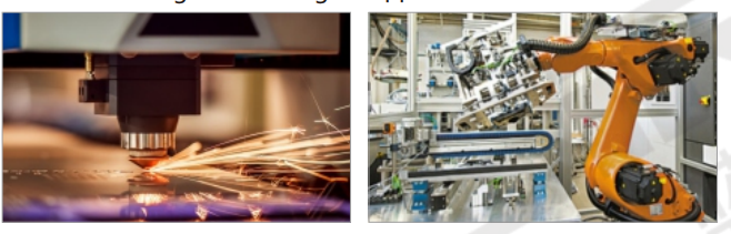
The application of laser cutting and welding
Applications on mechanical arms
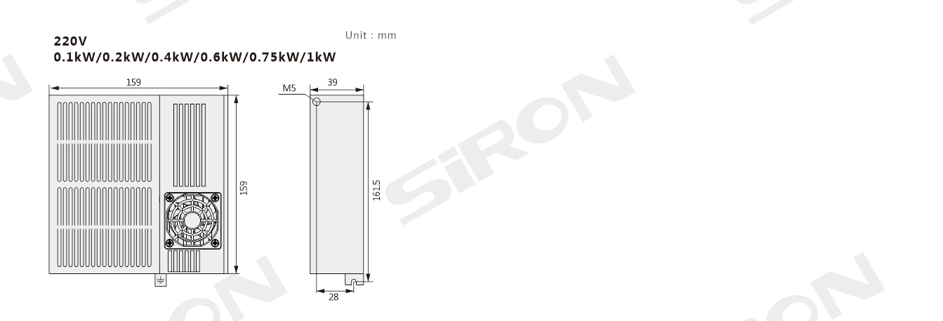
Outline Drawing
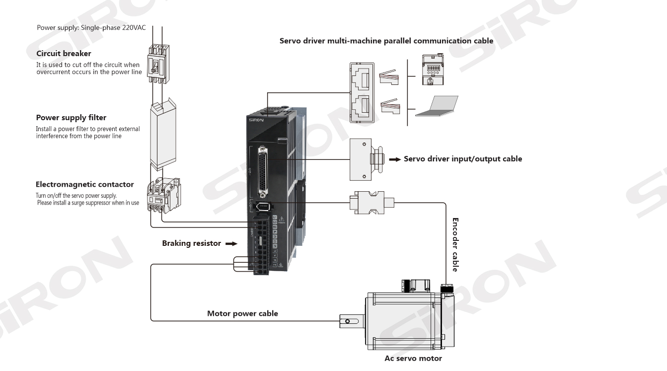
Wiring Diagram