Please Choose Your Language
close
Choose Your Site
Global
Social Media


| Quantity: | |
|---|---|
| PDF Export | |


K039-1 series
SiRON
8543709990
About selection
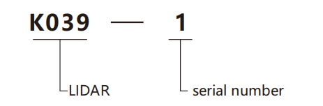
Selection example: K039-1 indicates K039 series, 1 serial number.
Specifications
| Name | High precision single line LiDAR | ||||
| Model | K039-1 | ||||
| Appearance |  TOF principle TOF principle | ||||
| Size | 62×62×83mm | Power supply | DC9~28V | ||
| Principle of ranging | Pulse TOF | Rated power | <1.5W(no load) | ||
| Laser wavelength | 905nm | Starting power | <3W(no load) | ||
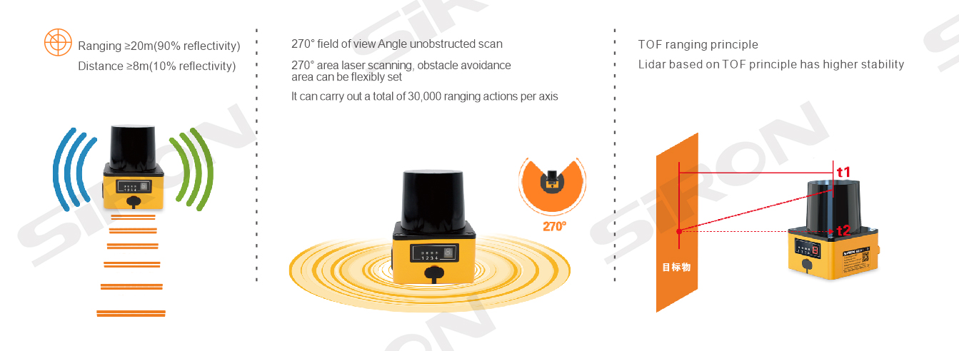
| Maximum detection range | ≥20m(90%reflectivity);≥8m(10%reflectivity) | Pilot lamp | 4(3 area signals,1 fault signal) | ||
| Detection range | 270° | Communication interface | USB-TYPC C(Serial port)&RJ45(Network port) | ||
| Sample rate (customizable) | 20KHz | Operating temperature | -10~+55℃ | ||
| Sweepfrequency | 10Hz | 20Hz | Storage temperature | -20~+70℃ | |
| Horizontal angular resolution | 0.18° | 0.36° | Class of protection | IP65 | |
| Response time | 100ms | 50ms | Anti-optical interference | 100000Lux | |
| Ranging accuracy | ±30mm | Sinusoidal frequency | 10Hz~1000Hz,acceleration 5g,three axes,10 cycles per axis | ||
| Start-uptime | 8s | Random vibration frequency | 55Hz~250H,Gr.m.s=4.24g,three axes,5 hours for each axis | ||
| Number of channels | 15(each channel contains 2 detection areas) | Impact resistance | The acceleration is 50g,the pulse is 3ms,and the impact of each axis is 5000 times,a total of 30000 times | ||
| Switching input | 4 | Weight | 171g | ||
| Switching output | 4(2 NPN area warning signals,1 for NPN OSSC security output signals) | ||||
Connect the device
*connection
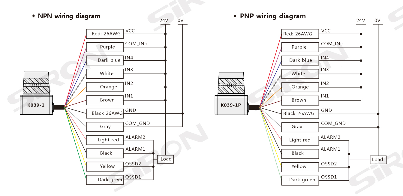
The wire sequence and function correspondence for K039-1 is shown in the table below, with a total of 16 wires.The connection diagram is illustrated in Figure 1. The device is also equipped with a TYPE‑C USB cable, which can be connected to a PC or other display devices for zone configuration and point cloud visualization. Alternatively, it can be connected to a PC or other equipment via an **Ethernet cable** for zone configuration and point cloud display.
*Wire Sequence & Function Correspondence Table
| Line number | Colour | Signal definition | Signal descnption |
| 1 | Red 2 6 A W G | VcC | Operating Power VCC |
| 2 | Black 2 6 A W G | GND | Operating Power GND |
| 3 | light red | ALARM2 | Two independent NPN outputs. ON state: maximum IOUT=200mA, VOUT≥COM_IN±2V; OFF state: IOUT<1mA, VOUT<2V. It is ON when there is no obstacle in the alarm area and OFF when there is an obstacle. |
| 4 | Balck | ALARM1 | |
| 5 | Yellow | OSSD2 | Two independent NPN outputs. ON state: maximum IOUT=200mA, VOUT≥COM_IN±2V; OFF state: IOUT<1mA, VOUT<2V. ON when no obstacle is in the protected area, OFF when there is an obstacle. |
| 6 | Dark green | OSSD1 | |
| 7 | Dark blue | IN4 | Zone group selection signal: Switching between multiple protected zones is realized via changing the input signals of IN1, IN2, IN3 and IN4. |
| 8 | Whie | IN3 | |
| 9 | Orange | IN2 | |
| 10 | Brown | IN1 | |
| 11 | Grey | COM_GND | Protection I/O GND |
| 12 | Purple | COM_IN+ | Protection I/O Power |
| 13 | Pink | OUT_RX+ | Ethernet Input + |
| 14 | Transparency | OUT_RX- | Ethernet Input – |
| 15 | Light green | OUT_TX+ | Ethernet Output + |
| 16 | Light blue | OUT_TX- | Ethernet Output – |

Dimension

Wiring diagram