Please Choose Your Language
close
Choose Your Site
Global
Social Media


| Quantity: | |
|---|---|
| PDF Export | |


M213
SiRON
8503009090
About selection
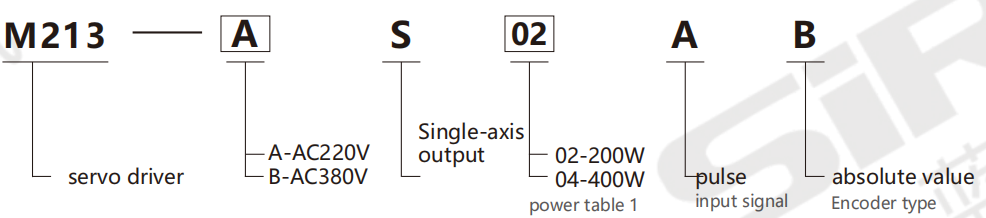
Selection example: M213-AS02AB represents the M213 series servo driver, with a power supply voltage of AC220V, single-axis output mode, power of 200W, input signal of pulse, and encoder type of absolute value.
Note: 1. Power supply voltage AC220V: The power selectable range is 200 to 5000W. Power supply voltage AC380V: Power selectable range 1800-7500W.The M213 series servo drives can be matched with M203 and M205 series servo motors.
Table 1: Power
| Voltage | AC 220V | ||||||||||
| Code | 02 | 04 | 08 | 15 | 22 | 30 | 50 | ||||
| Power | 200W | 400W | 750W | 1500W | 2200W | 3000W | 5000W | ||||
| Rated current | 2A | 2.8A | 5.5A | 10A | 12A | 16A | 25A | ||||
| Voltage | AC 380V | ||||||||||
| Code | 15 | 25 | 35 | 55 | 75 | ||||||
| Power | 1800W | 3000W | 3800W | 5500W | 7500W | ||||||
| Rated current | 5A | 8A | 12A | 16A | 20A | ||||||
Specification
| Name | M213 series servo drive | ||
| Iudutpower | Control method | Three-phase PWM converter sinusoidal wave drive | |
Main circuit power supply | Three-phase 220VAC/three-phase 380VAC(-15 to +10%,50 to 60Hz) | ||
Control power | Three-phase 220V:Single-phase 220VAC(-15 to +10%,50 to 60Hz);Three-phase 380V:None | ||
Rated current | 220V | 0.2kW/2A,0.4kW/2.8A,0.75kW/5.5A,1.5kW/10A,2.2kW/12A, 3kW/16A,5kW/25A | |
| 380V | 1.8kW/5A,3kW/8A,3.8kW/12A,5.5kW/16A, 7.5kW/20A | ||
| Encoder feedback | absolute encoder | ||
| Tmperatureandhumidityenvironment | Use environment temperature | 0~45℃ | |
Storage temperature | -20~65℃ | ||
Use environment humidity | Below 20 to 85%RH(no condensation) | ||
| Storage environment humidity | Below 20 to 85%RH(no condensation) | ||
| Use to preserve ambient air | Indoors (without direct sunlight),free from corrosive gases,flammable gases,oil mists and dust | ||
| Altitude | Below 1,000 meters in altitude | ||
| Vibration | Below 5.8m/s 2(0.6G),10~60Hz(cannot be used continuously at resonant frequency) | ||
| nsulation withstand voltage | Between beginner and FG,AC1500V for 1 minute | ||
| Function introduction | I0 input | 4 Inpt(DC24V optocoupler solation)can select input functions acording o parameters servo ON,Paction,prohibited foward rotation,prohibited reverse rotation, alarm reset,forward rotation torgue limi Reverse rotation torquelimit,control mode switching,zero position fixed,devition zeroing,internal set speed switching*2, motor selection direction switching |
| IO output | Three-chanel optocoupler isolated output;Output funtions can be selected based on parameters alam output,positioning proximity,consistent speed detection, motor rotation detection,servo preparation,torque limit,speed limit,brake release. | |
| Pulse input | Differential input:500K;Collector open circuit:200K Supports pulse+direction,AB orthogonal pulse,CW+CCW pulse | |
| Pulse output | Phase A and Phase B:Differential output,with arbitrary frequency division.Phase Z:Differential output or collector open circuit output | |
| Internal speed command | Three speeds are distributed through the input terminal | |
| Overload capacity | Maximum three times the torque | |
| Analog input | Input differential ±10V,one single-ended 0 to 10V,and switch according to the control mode | |
| Communication function | Modbus Communication | |
| Control mode l | 12 control modes Position control,speed control,torque control,internal speed,position/speed control,position/torque control,speed/torque contral, internal speed/position,internal speed/speed,internal speed/torque,speed/zero clamping,position control/command prohibition | |
| Regenerative resistance | 400W:No external regenerative resistor;Over 750W:Yes |
Application
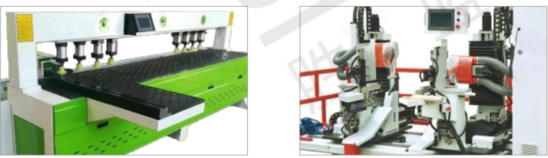
The application of woodworking side hole machines
The application of CNC double-end tenoning machine
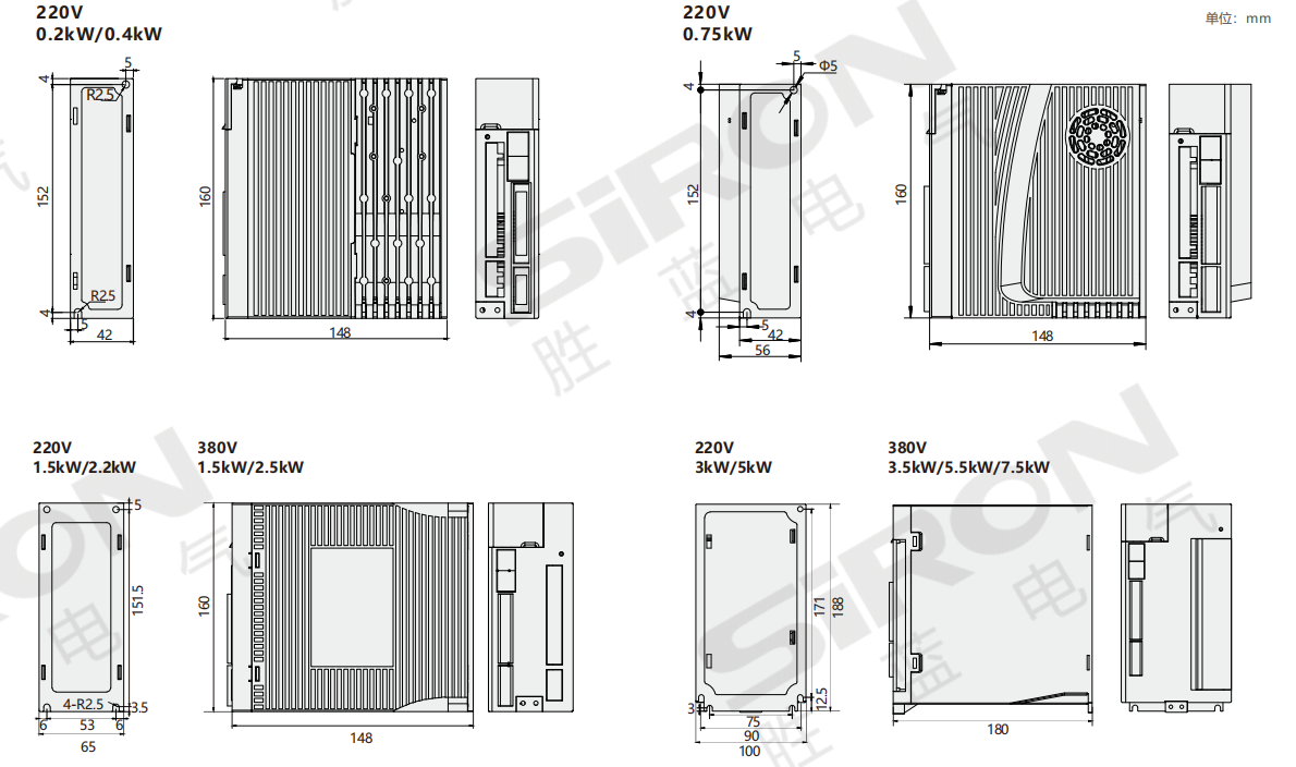
Outline Drawing
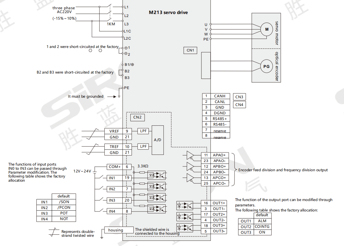
Introduction of Terminals
 | Solder pins | Definition | Definition |
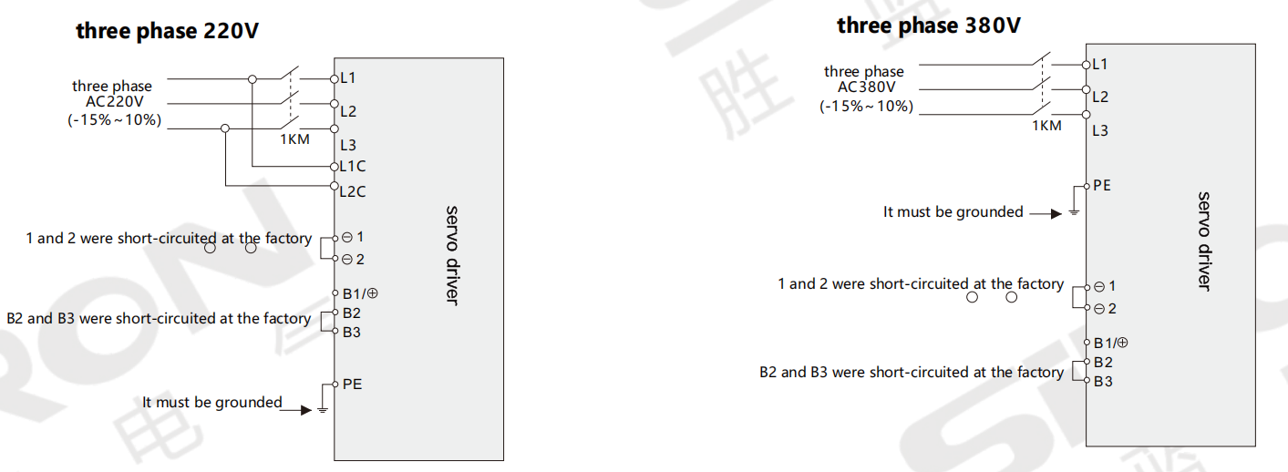
| L1、L2、L3 | Main power terminal | three phase AC 220V(-15%~10%,50/60Hz) | |
| L1C、L2C | Control power terminal | single phase AC 220V(-15%~10%,50/60Hz) | |
| -1、-2、 | DC reactor terminal | ex-factory,-1.一2 have been short-circuited | |
| B1/+、一B2、B3 | Brake resistor terminal | When using an external braking resistor, +Connect the braking resistor between B1 and B2 When using an internal braking resistor,Short-circuit B2 and B3(B2 and B3 were short-circuited at the factory)。 | |
| U、V、W、 | Motor terminal and grounding terminal | It must correspond one-to-one with the UVW terminals of the motor | |
| CN1 | Motor encoder terminal | Please pay attention to the terminal definition.For details,please refer to 2.6.2 of the manual | |
| CN2 | Functional IO terminal | Please pay attention to the terminal definition.For details,please refer to 2.6.3 of the manual | |
| CN3 | Communication terminal | Please pay attention to the terminal definition.For details,please refer to 2.6.1 of the manual | |
| CN4 |
Main circuit diagram
Location Mode Wiring Diagram
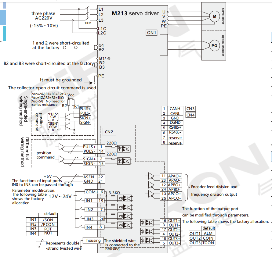
Conventional position control methods typically involve pulse, direction, alarm output, alarm clearance, brake output, etc. The control line wiring and definition are as follows:
25-core control terminal
| Servo 25corehigh density terminal | System side | Define |
| 1 | Pulse + | Resistors need to be connected in series according to different pulse voltages |
| 14 | Pulse | / |
| 2 | Direction + | Resistors need to be connected in series according to different pulse voltages |
| 15 | Direction | / |
| 16 | ALM+ | ALM+ |
| 3 | ALM- | ALM- |
| 6 | Public | Connect to |
| 19 | COM+ | Enable |
| 18 | InlBrake+ | BK+ |
| 5 | Brake | BK- |
The relevant parameter Settings are as follows:
| Parameter | Numerical value | Meaning |
| PA100 | 400 | Speed loop gain |
| PA101 | 2000 | Integral time of the velocity loop |
| PA102 | 400 | Position loop gain |
| PA005 | 98 | Motor model:130-15015(MG) |
| PA006 | 20 | Motor manufacturer code |
| PA202 | 1 | Electronic gear ratio molecule |
| PA203 | 1 | The electronic gear is larger than the female |
| PA509 | 9901 | External enabling |
| PA514 | 30 | BK defines allocation |
| PA205 | 0 | Position acceleration and deceleration time ms |
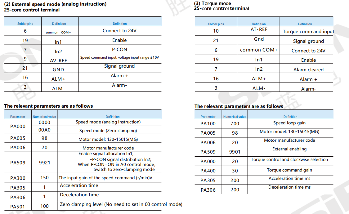
Speed/Torque Mode Wiring Diagram
(1) Internal speed mode 25-core control terminal
| Solder pins | Definition | Definition |
| 6 | common COM+ | Connect to 24V |
| 19 | In1 | SON enable |
| 7 | In2 | P-CON direction |
| 20 | In3 | NCL |
| 8 | In4 | PCL |
| 16 | ALM+ | Alarm + |
| 3 | ALM- | Alarm- |
The relevant parameters are as follows:
| Parameter | Numericalvalue | Definition | |
| PA000 | 30 | Internal velocity mode | |
| PA005 | 4 | Motor model 80-02430(MG) | |
| PA006 | 20 | Motor manufacturer code | |
| PA100 | 400 | Speed loop gain | |
| PA509 | 9921 | Enable signal allocation In1;Direction signal distribution In2 | |
| PA510 | 3400 | NCL signal distribution In3;PCL signal distribution In4 | |
| PA301 | 100 Sat byhe custema hasdo | NCL=ON,Motor Speed SPEED1 | |
| PA302 | 200 Sat by the ousnemar tamal | NCL=ON、PCL=ON,Motor Speed SPEED2 | |
| PA303 | 300 | Sat by me ouszemmrt amale | PCL=ON,Motor Speed SPEED3 |
| PA305 | 200 | Acceleration time ms | |
| PA306 | 200 | Deceleration time ms | |