Please Choose Your Language
close
Choose Your Site
Global
Social Media


| Quantity: | |
|---|---|
| PDF Export | |


T330-D
SiRON
8517623990
About selection
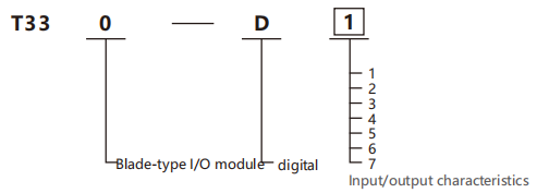
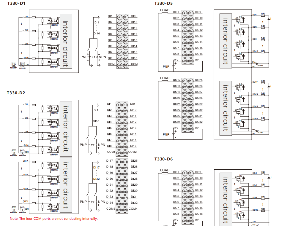
Selection example: T330-D1 represents the blade-type I/O module series.
It features 16-channel digital input and 0-channel digital output.
Input/Output Characteristics
| Code | Input | Output |
| 1 | 16 channels DI | 0 channels DO |
| 2 | 32 channels DI | 0 channels DO |
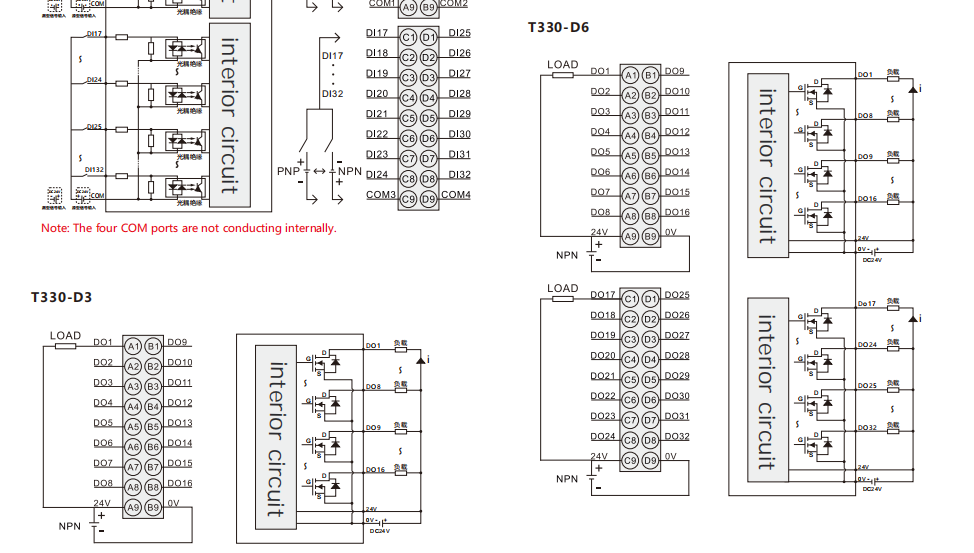
| 3 | 0 channels DI | 16 Channel digital(transistor)output(NPN) |
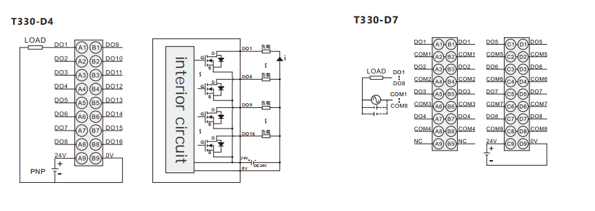
| 4 | 0 channels DI | 16 Channel digital(transistor)output(PNP) |
| 5 | 0 channels DI | 32 Channel digital(transistor)output(PNP) |
| 6 | 0 channels DI | 32 Channel digital(transistor)output |
| 7 | 0 channels DI | 8 Channel ssr output |
Specifications
| Powerparameters | |
| Usys-Ratedvdtageofthe bus input powersupply | 5V DC+20%1-15%(4.25V DC~6V DC) |
| Usys-Ratedcurrentof the bus input powersuppy | Input :<50mA(typical value at 5V Dc),Output:<60mA(typical value at |
| Uout-Ratedvotage ofthe power input | 24VDC+20%115%(20.4V DC~28.8VDC) |
| Uout-Ratedcurrent of the powerinput | 4A(typical at 24V DC),Solid-state relay:1A(typical at 24V DC) |
| Uout-And-reverse inserfion prohecion for power input | support |
| Module-Anb-power faluredifuslon prolecfon | support |
| Ennironmental condifions | |
| Alowable ambient temperature (during operafion) | -40~75℃ |
| Alowable ambient temperature (for storage) | -40~85℃ |
| Protecfion type | IP20 |
| Paolufion grade | 2 |
| Operafing alfitude | 0~2000m |
| Relative humidity (without ondens afion) | 5~95%RH |
| Connecfon parameters | |
| Connecfon technology | PUSH-IN Typeterminal block |
| Connecfion type | System/On-site power supply/input |
| Conductor cimping area | 26~16AWG/0.2~1.5mm² |
| Stip length | 10mm |
| Instalation method | DIN-35 |
| Shell material | PC plastic |
Input and output parameters
| Switch input module | T330-D1 | T330-D2 | |
| Number of channels | 16 | 32 | |
| Data size | 2 Byte | 4 Byte | |
| Eror diagnosis | Communication diagnostic | ||
| Signal type | NPN/PNP | ||
| Signal type | "ON"signal voltage | Pressure difference >11VDC(pressure difference from the common terminal input) | |
| "OFF"signal voltage | The pressure difference is less than 5VDC(the pressure difference from the common terminal input) | ||
| Connection type | lines shooting system | ||
| Input impedance | >7.5kΩ | ||
| Hardware response time | 100us/100us | ||
| Isolation status | yes | ||
| Indicator light status | When the input is valid,the input indicator light willbe on(controlled by software) | ||
| Filtering time configuration | Supports independent configuration for each single channel. | ||
| Synchronization mode | Supports synchronization within the same coupler group. | ||
| IO mapping | Supports bit-wise,byte-wise and word-wise mapping modes. | ||
| Switching output module | T330-D3 | T330-D4 | T330-D5 | T330-D6 | |
| Signaltype | NPN | PNP | PNP | NPN | |
| Protaction function | Over-temperature shutdown: Min.150℃/Typ.175℃ Overcurrent protection:3A;Short-circuit protection supported. | Over-temperature shutdown: Min.150℃/Typ.175℃ Overcurrent protection:1A;Short-circuit protection supported. | Over-temperature shutdown: Min.150°℃/Typ.175℃ Overcurrent proection:1A;Short-circuit protection supported. | Over-temperature shutdown: Min.150℃/Typ175℃ Overcurrent protection:3A;Short-circuit protection supported. | |
| Signaltype | "ON'signal voltage | OV DC | 24V DC | 24V DC | OV DC |
| "OFF’signal voltage | High configuration,leakage current<0.1mA | ||||
| Input rated voltage | 24V | 24V power input | |||
| oV | 0Vinput | ||||
| Output reduction | When operating at 55℃,derating by 50%(while the out put current of ON does not exceed 2A)Or derating by 10 ℃when all output points are ON | When operating at 55℃,derating by 50%(while the output current of ON does not exceed 4A)Or derating by 10℃ when all output points are ON | |||
| Numberof channels | 16 | 32 | |||
| Data size | 2 Byte | 4 Byte | |||
| Output load(resistance load) | 0.5A per point,4A per module | 0.5A per point,8A per module | |||
| Output load(inductance load) | 7.2 W per point,24 W per module | 7.2W per point,48W per module | |||
| Output load(light bulb load) | 5W per point,18W per module | 5W per point,36 W per module | |||
| Connection type | lines shooting system | ||||
| Switching frequency | Resistive load:100Hz,inductive load:0.5Hz,electric lamp load:10Hz | ||||
| Hardware response time | 100us/100us | ||||
| Isalation status | yes | ||||
| Indicator light status | When the output is valid,the output indicator light will be on(controlled by software) | ||||
| Emror diagnosis | Communication diagnosis,power supply diagnosis,channel overcurrent diagnosis | ||||
| Communication failure output status mode | Maintain the current value and output according to the replacement value (configurable) | ||||
| Overcurment fault output status mode | Automatic retry and output stop(configurable) | ||||
| Synchronizafion mode | Supports synchronization within the same coupler group. | ||||
| I0mapping | Supports bit,byte and word mapping modes. | ||||
| Switch quanity output relay module | T330-D7 | |||
| Channel quantity | 8 | Contact resistance | ≤100mΩ | |
| Signal type | Relay normally open output | Mechanical lfespan | 20 million times | |
| Output voltage level | 250VAC/30VDC | Electrical lifespan | 10万次 | |
| Input rated voltage | 24V | 24V power input | Isolation status | yes |
| 0V | OV input | Protection function | no | |
| Signal type | "ON"signal voltage | ≤10ms | Indicator light status | When the output is valid,the output indicator light will be on (controlled by software) |
| "OFF"signal voltage | ≤5ms | Data size | 2 Byte | |
| Output reduction | When operating at 55℃,derate by 50%(while the output current ON does not exceed 1A),or derate by 10℃ when all output points are ON | Eror diagnosis | Communication diagnosis,power supply diagnosis | |
| Communication failure output status mode | Keep the current value and output according to the replacement value | |||
| Output load (resistorload) | 2A per point,8A per module | Synchronization mode | Supports synchronization within the same coupler group. | |
| Output load (inductor load) | 2A per point,8A per module | I0mapping | Supports bit,byte and word mapping modes. | |
| Output load (light bulb load) | 30W per point,120W per module | |||
| Minimum DC load | 5 V D C | |||
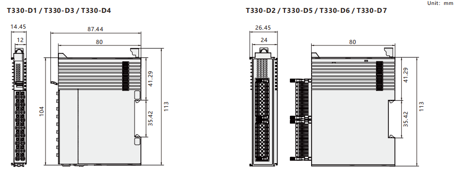
Dimension
Wiring diagram