Please Choose Your Language
close
Choose Your Site
Global
Social Media


| Quantity: | |
|---|---|
| PDF Export | |


T330-A
SiRON
8517623990
About selection
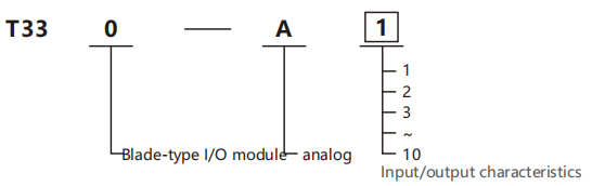
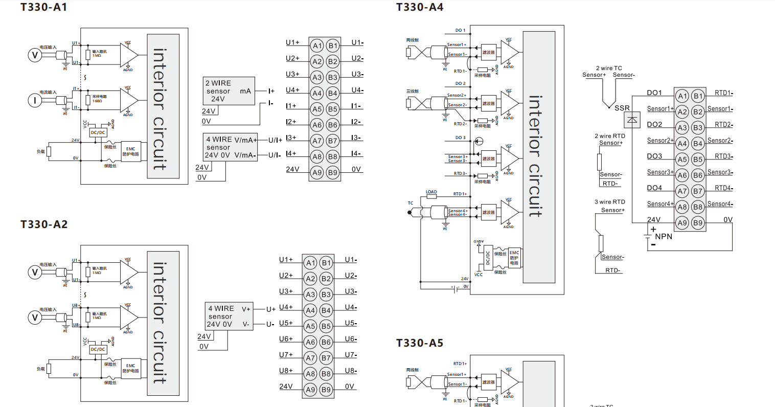
Selection example: T330-A1 represents the blade-type I/O module series. Analog, input/output characteristics: 4-channel analog input, 0-channel analog output
Input/Output Characteristics
| Code | Input | Output |
| 1 | 4 channels Al(0~10V,0~20mA) | 0 channels AO |
| 2 | 8 channels AI(0~10V) | 0 channels AO |
| 3 | 8 channels AI(0~20mA) | O channels AO |
| 4 | 4channels Al(Themal resistance/thermocouple RTD,include PID) | 0 channels AO |
| 5 | 4channels Al (Thermal resistance/thermocouple RTD) | 0 channels AO |
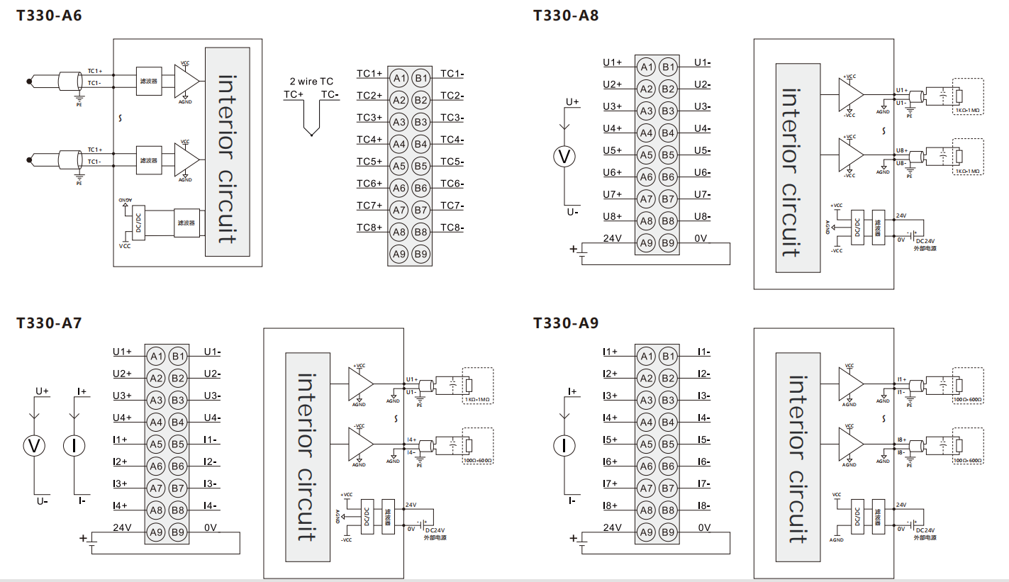
| 6 | 8 channels Al(thermocouple TC) | 0 channels AO |
| 7 | 0 channels Al | 4 channels AO(0~10V,0~20mA) |
| 8 | 0 channels Al | 8 channels AO(0~10V) |
| 9 | 0 channels Al | 8 channels AO(0~20mA) |
| 10* | 0 channels Al | 4 channels AO(0~1A,Solenoid drive) |
Specifications
| Powersupply parameters | T330-A1/T330-A2/T330-A3 |
| Usys-Rated voltage ofthe bus inputpower supply | 5V DC+20%/-15%(4.25V DC~6V DC) |
| Usys-Rated current of the bus input power supply | <50mA |
| Uin-Rated voltage of the power input | 24VDC+20%/-15%(20.4V DC~28.8VDC) |
Uin rated input current of the power supply | <50mA none Power Distribution |
<250mAPower Distribution | |
| UINpowerinput anti-reverse insertion protection | support — |
| Powersupplyparameters | T330-A4/T330-A5/T330-A6 |
| Usys-Rated voltage ofthe bus inputpower supply | 5V DC+20%/-15%(4.25V DC~6V DC) |
| Usys-Rated current of the bus input power supply | <60mA(5VDC Typical value) |
| Power supplyparameters | T330-A7/T330-A8/T330-A9 |
| Usys -Rated voltage of the bus input power supply | 5V DC+20%/-15%(4.25V DC~6V DC) |
| Usys-Rated curent of the bus input powersupply | <50mA(Typical value 5V DC) |
| Uout-Rated voltage of the power input | 24VDC+20%/-15%(20.4V DC~28.8V DC) |
| Uout -Rated current of the power input | <200mA |
| Uout-Anti-reverse insertion protection forthe power input | support |
| Connection parameters | |
| Connection technology | PUSH-IN terminal blocks |
| Connection type | System/On-site power supply/input |
| Conductor crimping area | 26~16AWG/0.2~1.5mm² |
| Strip length | 10mm |
| Installation method | DIN-35 |
| Shell material | PC plastic |
| Environmental conditions | |
| Allowable ambient temperature(during operation) | -40~75℃ |
| Allowable ambient temperature(for storage) | -40~85℃ |
| Protection type | IP20 |
| Pollution grade | 2 |
| Operating ltitude | 0~2000m |
| Relative humidity(without condensation) | 5~95%RH |
Input and output parameters
| Analog voltage/current input module | T330-A1 | T330-A2 | T330-A3 |
| Number of channels | 4 | 8 | 8 |
| Signal type | Voltage/Current | Voltage | Current |
| Measurement range | Disable,±10V、0~10V、2~10V、 ±5V、0~5V、1~5V 0~10mA、0~20mA、4~20mA、 | Disable、±10V、0~10V、2~10V、 ±5V、0~5V、1~5V | Disable,0~10mA,0~20mA,4~20mA |
| Voltage/current protection | 24V/30mA | 24V | 30mA |
| Input diagnosis | Over-limit detection,2~10V,1~5V /4~20mA s upport for disconnection detection | 2~10V、1~5V Support disconnection detection | Over-limit detection,4-20mA supports disconnection detection |
| Input accuracy | ±0.1%(±10V full range)/(20mA full range) | ±0.1%(full range) | ±0.1%(full range) |
| Inputimpedance | >400KΩ | >400KΩ | |
| Sampling impedance | ≤250Ω | ≤250Ω | |
| Sampling period | 1ms(4 channels) | 1.6ms(8 channels) | |
| Data size | 8 Byte | 16 Byte | |
| Temperature drift | ±50ppm/K | ||
| Channel reverse polarity protection | support | ||
| Channel prevention of 24V misconnection | support | ||
| Independent channel enable configuration | support | ||
| Diagnostic reporting function configuration | support | ||
| Connection type | 2-wire power distribution,4-wire non-power distribution | ||
lsolation status | No isolation between interface channels,isolated between interface and bus. | ||
| nputaction display | Input channel indicator keeps steady on when input signal is active (software-controlled). | ||
| Filtering method | Sliding window filtering,debounce filtering,50Hz/60Hz power frequency anti-interference. | ||
| Eror diagnosis | Communication diagnosis,power diagnosis,channel over-limit diagnosis,channel disconnection diagnosis. | ||
| IO mapping | Supports word mapping mode | ||
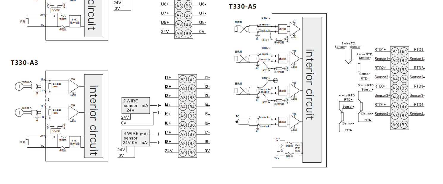
| Analog thermal resistancelequivalent input module | T330-A4 | T330-A5 | T330-A6 | |
| Number of channels | 4 | 4 | 8 | |
| Signal type | NPN | - | ||
| Module type | Thermal resistance and thermocouple measurement module (including PID) | RTD &Thermocouple Measurement Module | Thermocouple Measurement Module | |
| Sensor type | Pt100,Pt200,Pt500,Pt1000,Ni100,Ni120,Ni200,Ni500,Ni1000,Cu10,Cu50,Cu53,Cu100,KTY83-110, KTY83-120,KTY83-121,KTY83-122,KTY83-150,KTY83-151,KTY84-130,KTY84-150,KTY84-151,40Ω,300Ω,500Ω, 1kΩ,2kΩ,K,E,T,J,B,S,R,N,C,L,±15.625mV,±31.25mV,±62.5mV,±125mV,±250mV,±500mV,±1000mV,±2000mV | Themocouple input,thermocouple type:K、E、T、J、 R.N、C、L、±15.625mV、±31.25mV、±62.5mV、 ±125mV、±250mV、±500mV、±1000mV、±2000mV | ||
| Sampling period | RTD:250ms/TC:500ms、RTD:500ms/TC:1000ms、RTD:1000ms/TC:2000ms、 RTD:320ms/TC:640ms(50Hz Frequency Suppression)、 RTD:266ms/TC:532ms(60Hz Frequency Suppression) | 500ms、1000ms、2000ms、 1280ms(50Hz Frequency Suppression)、 1064ms(60Hz Frequency Suppression) | ||
| Inputaction display | When the input signal is valid,the channel input indicator light remains on constantly.When the channel diagnosis is turned on,When the input sign al is invalid,the channel input indicator light flashes | When the output is valid,the output indicator light willbe on(controlled by software) | ||
| Signal type | "ON"signal voltage | OVDC | - | - |
| "OFF"signal voltage | High configuration,leakage current<0.1mA | - | - | |
| Connection type | 1-wire system | - | - | |
| Connection method | 2 wire system、3 wire system | 2 wire system、3 wire system、4 wire system | 2 | |
| Data size | - | 8 Byte | 16 Byte | |
| Control output type and number/Ch | Voltage Output (for SSR drive),1 point/Ch | - | - | |
| Maximum load current | 0.05A per point,0.2A per module | - | - | |
| Hardware response time | 100us/100us | - | - | |
| Temperature drift | ±50ppm/K,±0.375% | |||
| Channel diagnosis | Upper limit alarm,lower limit alarm,broken wire alarm,overflow error |
| Diagnostic reporting function configuration | support |
| Frequency interference suppression | Supports 50Hz/60Hz suppression |
| Display sensitivity | 0.1℃ |
| Compensation method | Internal cold junction compensation |
lsolation | Isolated between interface and bus,isolated between terminals and power supply,non-isolated between channels |
| Filtering method | Sliding window filtering,debounce filtering,50Hz/60Hz power frequency rejection |
| Error diagnosis | Communication diagnosis,power diagnosis,channel overrange diagnosis,channel open circuit diagnosis |
| IO mapping | Supports word-based mapping |
| Analog voltage/current output module | T330-A7 | T330-A8 | T330-A9 |
| Number of channels | 4 | 8 | 8 |
| Signal type | Voltage/Current | Voltage | Current |
| Measurement range | Disable,±10V、0~10V、2~10V、 ±5V、0~5V、1~5V 0~10mA、0~20mA、4~20mA、 | Disable、±10V、0~10V、2~10V、 ±5V、0~5V、1~5V | Disable,0~10ma,0~20ma,4~20ma |
| Output load | Voltage(>1kQ);Current(0~10mA:<1.5kQ; Others:<600Ω) | >1kΩ | 0~10ma:<1.5kΩ,others:<600Ω |
| Output action display | When the output is valid,the output indicator light will be on (controlled by software) | When the output is valid,the output indicator light will be on | When the output signal is valid,the indicator light remains on constantly |
| Error diagnosis | Communicaton diagnosis,power supply diagnosis, output open circuit(effective when current is output) | Communication diagnosis,power supply diagnosis | Communication Diagnosis,Power Diagnosis,Output Open Circuit |
| Conversion of digital quantity range | -20000~20000,-32000~32000,-27648~27648 | 0~20000,0~32000,0~27648 | |
| Output accuracy | ±0.1% | ±0.1%(Full-scale Value) | |
| lsolation setting | There is no isolation between interface channels,but the powersupply is isolated from the interface,and the interface is isolated from the bus | The interface channels are not isolated from each other,but the interfaces are isolated from the bus.500VAC | |
| Output response time | 10%to 90%step:<100ms | ||
| Diagnostic detection | Communication diagnosis,power supply diagnosis,output open circuit | ||
| Diagnostic reporting function configuration | support | ||
| Connection type | 2-wire distribution,4-wire non-distribution | ||
| Temperature drift | ±50ppm/k | ||
| Output status configuration after shutdown | Maintain the current output or output the preset value | ||
| Stop mode | Stop at fault mode,stop refreshing. | ||
| Size of IO process data | 16byte | ||
| Synchronization mode | Supports synchronization within one coupler group | ||
| IO mapping | Supports word mapping mode | ||
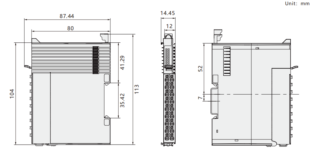
Dimension
Wiring diagram