
Please Choose Your Language
close
Choose Your Site
Global
Social Media


| Quantity: | |
|---|---|
| PDF Export | |


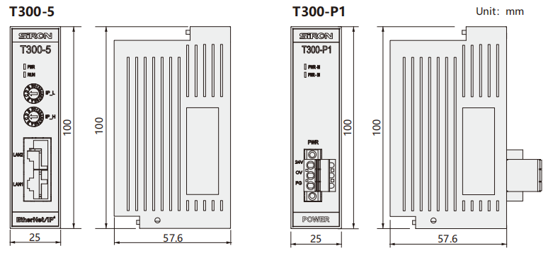
T300-5
SiRON
8517623990
About selection
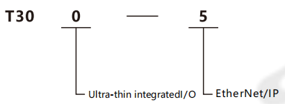
Example:T300-5 represents the ultra-thin integrated I/O series,and the coupler protocol is EtherNet/IP.
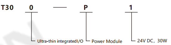
Example:T300-P1 represents ultra-thin integrated I/O series,power module,24VDC,30W.
Specifications
| Model | T300-5 | Model | T300-P1 | |
| Bus protocol | EtherNet/IP | Working power supply | DC24V | |
| Connection mode | 2*RJ45 | Output voltage | DC24V | |
| Communication rate | 100Mb/s | Output curent | Max1.25A | |
| Communication distance | 100m(Station distance) | Voltage error | ±3% | |
| Rated input voltage | DC 24V | Ripple rate | 50mVP-P | |
| Effective power supply range | DC 18~36V | Operating temperature range | 0~50℃ | |
| Electrical isolation | AC500V | Storage temperature range | -20~125℃ | |
| Power status display | GreenRUN LED light | |||
| Network port indication (Blnking when there is data exchange) | Green Link1 LED light correspond to LAN1 Green Link2 LED light correspond to LAN2 | |||
Environmental conditions
Transportation/storage | Temperature | -40~70℃ |
| Atmospheric pressure | 1080~660hPa(corresponding height is-1000~+3500m) | |
| Relative humidity | 10~95%,non condensing | |
| Fall | 1m,10times,Shipping Packages | |
| Working hours | Temperature | Horizontal installation:0~60℃;Vertical installation:0~40℃ |
| Atmospheric pressure | 1080~795hPa(corresponding height is-1000~+2000m) | |
| Relative humidity | 10~95%,Non condensation | |
| Concentration of severe environmental pollutants | Low salt mist,humidity,dust mist and other environments S02<0.5ppm,relative humidity<60%,non-condensing H2S<0.1ppm,relative humidity<60%,non-condensing |
Dimensions
Communication bus interface
The definition of the RJ45 communication interface is as follows green :
| Signal description | Description | |
| 1 | TD+ | sending signal+ |
| 2 | TD- | sending signal- |
| 3 | CT | centre tap |
| 4 | NC | reserve |
| 5 | CT | centre tap |
| 6 | RD+ | sending signal+ |
| 7 | RD- | sending signal- |
| 8 | GND | internally |
System indicator light definition
| Description | Color | |
| RUN | The operation indicator light is on when the system is running normally | green |
| Link1 | The operation indicator light is on when the system is powered on. It flashes when there is data exchange | green |
| Link2 |
Dip switch Sets the IP address
| Dip switch | IP1 | IP0 | ||||||
| Serial number | 1 | 2 | 3 | 4 | 5 | 6 | 7 | 8 |
| Corresponding bit | Bit7 | Bit6 | Bit5 | Bit4 | Bit3 | Bit2 | Bit1 | Bit0 |
The IP address is 192.168.0.IP1+IP0
IP1 and IP0 are respectively set by the 8-bit (one byte, in binary for m) dip switch in the figure
For example: Set IP 192.168.0.13:
Topological structure diagram


