Please Choose Your Language
close
Choose Your Site
Global
Social Media


| Quantity: | |
|---|---|
| PDF Export | |


T330-W
SiRON
8517799000
About selection
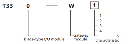
Selection example: T330-W3 represents the blade I/O module series, the CANopen Master gateway module, which is used for com munication with the Slave.
Gateway characteristics
| Code | Gateway |
| 1* | EtherCAT Slave gateway module,used for communication with Master |
| 2* | PROFINET Slave gateway module,used for communication with the Master |
| 3 | CANopen Master gateway module,used for communication with CANopen Slave devices. |
| 4* | 4-channelIO-Link Master gateway module for communication with IO-link sensors. |
| 5 | RS422/RS485/RS232 serial port module,supports Modbus RTU Master/Slave mode. |
Specification
| Power supply parameters | T330-W3 |
| Input power supply rated voltage at terminals | 24V DC(20.4V DC~28.8V DC) |
| nput power supplyrated currentat terminals | 5A(Typical value at 24V DC) |
| Usys-Backplane output power supply rated voltage | 5V DC(4.75V DC~5.25V DC) |
| Usys-Backplane output power supply rated current | 2A(Typical value at 5V DC) |
| Uin-Backplane output power supply rated voltage | 24V DC(20.4V DC~28.8V DC) |
| Uin -Backplane output power supply rated current | 4A(Typical value at 24V DC) |
| Power supply parameters | T330-W5 |
| Usys-Rated woltage of the bus input power supply | 5V DC+20%1-15%(4.25V DC~6V DC) |
| Usys-Rated cumentof the bus input power supply | <60mA(Typical value at 5V DC) |
| Uin -Rated voltage of the power input | 24VDC+20%115%(20.4V DC~28.8V DC) |
| Uin -Rated current of the power input | 4A(Typical value at 24V DC) |
| Uin-Anti-reverse insertion protection forpower input | SUPPORT |
| Module anti-power failure diffusion | SUPPORT |
| Connection parameters | |
| Connection technology | PUSH-IN terminal |
| Connection type | System/Field Power Supply /Input |
| Conductor crimping area | 26~16AWG/0.2~1.5mm² |
| Strip length | 10mm |
| Installation method | DIN-35 |
| Shell material | PCPlastic |
| Environmental conditions | |
| Alowable ambient temperature(during operation) | -40~75℃ |
| Alowable ambient temperature(for storage) | -40~85℃ |
| Protection type | IP20 |
| Pollution grade | 2 |
| Operating atitude | 0~2000m |
| Relative humidity (without condensation) | 5~95%RH |
| Gateway module | T330-W3 | ||
| Signal type | 1-channel CAN interface | Alarm function | Standard &enhanced diagnosis |
| Connection method | terminal | Ilsolation method | Galvanic isolation from field side |
| Communication protocol | CANOpen | Transmision medium | Cat5 twisted pair cable |
| Communication rate | Supports baud rate:10,20,50,100,125,250,500,1000 Kbps,adjustable | Maximumnumber of slave stations supported | 8 channels |
| Bus address stting | DIP switch configuration,bus address setting range:1~127 | Number of PDOs supported by a single slave stafion | Up to 10 groups of PDO |
| Transmission distance | The maximum length is1000meters,hich s actualyrelated to the baud rate and cabe impedance | Data size supported by asingle slave station using PDO | Max 128 bytes |
| Gateway module | T330-W5 | ||
| Module type | Communication gateway module | Data storage size | The maximum single channel is 128 bytes |
| Number of channels | 1 channels | Eror diagnosis | Active Reporting |
| Communication interface type | The module only supports one serial port communication 1 RS232 channel 1 RS485 channet;1 RS422 | Number of module supports | A single coupler can connect up to 6 of these modules. |
| Communication distance | RS232:Maximum 15m;RS422/RS485:Maximum 1200m | Number of channels | Up to 18 channels are supported |
| Isolation status | Yes,each channel is isolated from the internal circuit,but not isolated between channels | Modbus protocol | RTU |
| Terminal matching resistor | Short-circuit the near end of the terminal resistance port through the user's extemal wiring selection | Data transmission baudrate | 1200 bps~4687500 bps(default:9600 bps |
| Work mode | Modbus Master/Modbus Slave/Transparent Transmission(Default:Modbus Master) | Check bit | No check/odd check/even check |
| Communication interface | RS485/RS232/RS422(默认RS485) | Start bit | 1 bit |
| Data bit | 7-bit/18-bit(Default:8-bit;parity is required when configured to 7-bit) | Stop bit | 1-bit,2-bit(default:1-bit) |
| Response delay | The working mode is that when the slave station receives the message sent by the | Read timeout handling | Keep the last input value/reset the input value |
| Byte order conversion | master station,it responds to the master station with a delay,with the unit beingm When operating in transparent transmission mode,swap every two transmit/receive data positions | Slave station ID | Slave mode module ID number |
| Output load | Voltage standard value:24V,maximum curent:200mA;Voltage standard value:5V,maximum curent :500mA;Two output loads can be outputsimultaneously | ||
| Frame interval time | Interval time for re-transmission after the master receives the response frame from the slave;range:0~65535,unit:ms | ||
| Response timeout time | Timeout for master waiting for slave response,or response waiting timeout in transparent transmission mode. | ||
| Polling time | Delay from master receiving slave response frame to sending the next command;range:0~65535,unit:ms. | ||
Data output mode | Polling Mode /Event Trigger /Level Trigger/Rising Edge Trigger ecm tigera outpurocuswhenoutda hanos e troge comucnons ioed ohe hemate chamecntolod 1.Rioes tisecomumiao s ised he te materoame cotro wodanges from O to 1) | ||
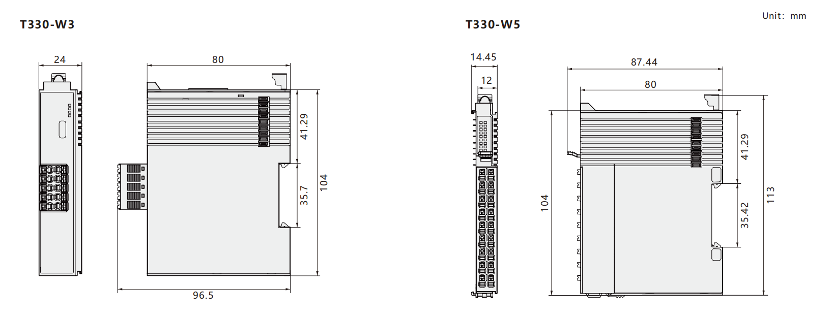
Dimensions
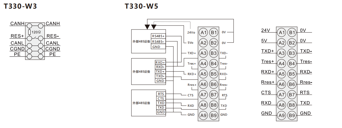
Wiring diagram