
Please Choose Your Language
close
Choose Your Site
Global
Social Media


| Quantity: | |
|---|---|
| PDF Export | |


M280-425/542/556/860-C
SiRON
8501109990
About selection
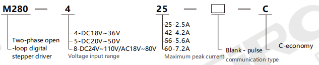
Selection example: M280-425 represents the M280 series two-phase open-loop digital stepper driver, with a voltage input range of DC18V to 36V, a maximum peak current of 2.5A, and a communication type of pulse type and economy type.
Specification
| Model | M280-425-C | M280-542-C | M280-556-C | M280-860-C | |
| Voltage input range(V) | DC18~36 | DC20~50 | DC20~50 | DC24~110/AC18~80 | |
| IMaximum peak current(A) | 2.5 | 4.2 | 5.6 | 7.2 | |
| Subdivision scope(ppr) | 400~6400 | 200~25600 | 200~25600 | 400~51200 | |
| Impulse response(KHz) | 0~200 | ||||
| Pulse form | Pulse +Direction | ||||
| Environmental parameters | Storage temperature | -20℃~65℃ | |||
| Usage temperature | 0℃~50℃ | ||||
| Vibration frequency | Less than 0.5G (4.9m/s 2),10Hz to 55Hz(non-continuous operation) | ||||
| Use humidity | 40-90%RH(No condensation) | ||||
| Insalationenvironmenl | Avoid places with dust,oil stains,corrosive gases,excessive humidity and strong vibration.Flammable gases and conductive dust are strictly prohibited | ||||
Dimensions
Driver Function Description
| Driver function | M280-425-C | M280-542-C | M280-556-C | M280-860-C | |
| Micro step fine score setting | The microstep division of the driver is set by two dip switches,SW5 and SW6.There are a total of 4 microstep divisions.When users set the divisions, they should first stop the driver's operation. For the specific setting of the microstep division, please follow the instructions on the driver panel | The microstep division of the driver is set by four dip switches from SW5 to SW8.There are a total of 15 microstep divisions.When users set the divisions,the y should fist stop the drive's operation.For the specific setting of the microstep division,please follow the instructions on the dniver panel | |||
| Output current setting | The output current of the driver is set by three switches from SW1 to SW3,and there are a totl of 8 output current Settings.For the specific setting of the output current,please refer to the instructions on the driver panel | ||||
| Automatic semi flow function | Users can set the automatic half-curent function of the driver through the SW4 switch."OFF"indicates that the static current is set to half of the dynamic current,and "ON"indicates that the static current and dynamic current are the same.In general applications,SW4 should besetto OFF to reduce the heat generation of the motor and driver and improve reliability.About 0.3 seconds after the pulse train stops,the current automatically drops by 50%(actual 55%),and the heat generation theoretically decreases by 65% | ||||
| Signal interface | PUL is the negative terminal of the control pulse signal,DIR is the negative terminal of the direction signal,ENAis the negative terminal of the enable signal,and OPTO is the positive terminal(5V common terminal)of the pulse/direction/enable signal. | PUL+and PUL-are the positive and negative terminals of the control pulse signal.DIR+and DIR-are the positive and negative terminals of thee direction signal;ENA+and ENA-are the positive and negative terminals of the enable signal | |||
| Motor interface | A+and A-are connected to the positive and negative terminals of the A-phase winding of the stepping motor.B+and B-are connected to the positive and negative terminals of the B-phase winding of the stepping motor.When the A and B phase windings are swapped,the motor direction can be reversed | ||||
| Power interface | It is powered by a DC power supply,with a working input voltage range of 18V to 36VDC, and a recommended working voltage of 24VDC | It is powered by a DC power supply.The working input voltage range is 20V to 50VDC,with a recommended working voltage of 36VDC.The power supply capacity is greater than 100W | It is powered by AC/DC power supply,with a voltage range of 24 to 110VDC or 18 to 80VAC.The terminals are not divided into positive and negative poles.It is recommended to use a48V DCpower supply with a power greater than 250W | ||
| Indicator light | The driver has two indicator lights,red and green.The green lightis the power indicator light.When the driver is powered on,the green light remains on constantly.The red light is the fault indicatorlight.When overvoltage or overcurrent faults occur,the fault light remains on constantly.After the fault was cleared,the red light went out.When a driver malfunctions,the fault can only be cleared by re-powering and re-enabling it | ||||
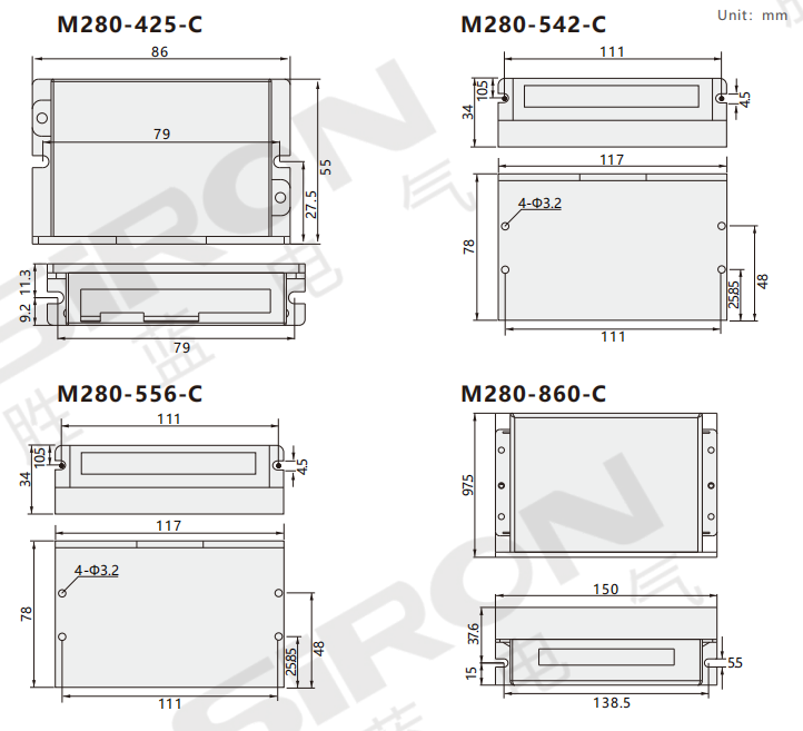
| Installation instructions | The external dimensions of the drive are:86x55x 20.5mm,for installationThe hole spacing is 79mm and it can be installed either horizontally or vertically (vertical installation is recommended).When installing,it should be usedlt is tightly attached to the metal cabinet to facilitate heat dissipation | The extermal dimensions of the driver are 117x78x34mm,and the installation hole spacing is 111mm.It can be installed either horizontally or vertically (vertical installation is recommended).When installing, it should be tightly attached to the metal cabinet to facilitate heat dissipation | The external dimensions of the driver are 150x97.5 x52.6mm,and the installation hole spacing is 138.5 mm.It can be installed either horizontally or vertically(vertical installation is recommended). When installing,it should be tightly attached to the metal cabinet to facilitate heat dissipation | ||
Current/Subdivision Settings
| Parameter setting Working current setting Micro stepsubdivision settingsettings | |||||||||||
 | Output peak current | SW1 | SW2 | SW3 | Steps/RPM | SW5 | SW6 | ||||
| 0.5A | ON | ON | ON | 400 | ON | ON | |||||
| 0.7A | OFF | ON | ON | 1600 | OFF | ON | |||||
| 1.0A | ON | OFF | ON | 3200 | ON | OFF | |||||
| 1.3A | OFF | OFF | ON | 6400 | OFF | OFF | |||||
| 1.6A | ON | ON | OFF | ||||||||
| 1.9A | OFF | ON | OFF | ||||||||
| 2.2A | ON | OFF | OFF | ||||||||
| 2.5A | OFF | OFF | OFF | ||||||||
| Parameter setting | Working current setting | Micro step subdivision settingsettings | ||||||||
 | Output peak curent | Output unifom curen | SW1 | SW2 | SW3 | Steps/RPM | SW5 | SW6 | SW7 | SW8 |
| 1.0A | 0.71A | ON | ON | ON | Default | ON | ON | ON | ON | |
| 1.46A | 1.04A | OFF | ON | ON | 400 | OFF | ON | ON | ON | |
| 1.91A | 1.36A | ON | OFF | ON | 800 | ON | OFF | ON | ON | |
| 2.37A | 1.69A | OFF | OFF | ON | 1600 | OFF | OFF | ON | ON | |
| 2.84A | 2.03A | ON | ON | OFF | 3200 | ON | ON | OFF | ON | |
| 3.31A | 2.36A | OFF | ON | OFF | 6400 | OFF | ON | OFF | ON | |
| 3.76A | 2.69A | ON | OFF | OFF | 12800 | ON | OFF | OFF | ON | |
| 4.2A | 3.0A | OFF | OFF | OFF | 25600 | OFF | OFF | OFF | ON | |
| 1000 | ON | ON | ON | OFF | ||||||
| 2000 4000 | OFF ON | ON | ON ON | OFF OFF | ||||||
| OFF | ||||||||||
| 5000 | OFF | OFF | ON | OFF | ||||||
| 8000 | ON | ON | OFF | OFF | ||||||
| 10000 | OFF | ON | OFF | OFF | ||||||
| 20000 | ON | OFF | OFF | OFF | ||||||
| 25000 | OFF | OFF | OFF | OFF | ||||||


