
Please Choose Your Language
close
Choose Your Site
Global
Social Media
Views: 0 Author: Site Editor Publish Time: 2026-06-16 Origin: Site


Automated manufacturing changes rapidly every single day. Standard photoelectric sensors often fail in tight machine spaces. They also struggle to meet strict micro-level detection tolerances. You need continuous high-speed throughput for maximum plant efficiency. However, achieving stable, drift-free sensing remains a difficult engineering challenge. Fast production lines easily misalign conventional sensors. This causes costly false triggers and unpredicted mechanical downtime. We aim to solve these common detection problems here. We provide automation engineers a rigorous, evidence-based evaluation framework. You will learn how to configure and optimize these critical devices. We cover practical best practices for advanced production line deployments. By following these guidelines, you can eliminate unpredictable sensing errors entirely.
Standardizing on a specific fiber optic amplifier requires evaluating the trade-off between response time (µs) and detection range.
Advanced hysteresis tuning and mutual interference prevention are non-negotiable for high-density mounting environments.
Selecting between a through-beam fiber sensor and a diffuse configuration dictates the baseline alignment precision and installation overhead.
Long-term reliability is driven by ambient light immunity, temperature drift compensation, and seamless PLC/IO-Link integration, not just initial unit cost.
Operational bottlenecks cripple automated manufacturing processes quickly. Conventional sensors often trigger falsely under demanding conditions. Highly reflective targets confuse standard receivers easily. Micro-components slip past wide sensor beams undetected. Vibrating web processes cause constant distance shifts. You need stable detection under these harsh mechanical conditions. Conventional units bounce light back unpredictably from shiny surfaces. We must define clear success criteria before purchasing new hardware. Success means achieving zero false positives consistently. Your machines might run over 2,000 units per minute. A single sensing error halts the entire production line. We also require successful integration into tight machine housing. Space remains a premium commodity on modern packaging lines.
You must perform a credibility check before upgrading your sensing hardware. A precision detection amplifier is not a universal magic fix. It introduces unique optical alignment complexity. It demands careful fiber unit selection tailored to the exact target. You cannot simply bolt it into an existing bracket. You must plan the optical geometry meticulously. We provide the technical grounding needed to evaluate these systems properly. When you understand the operational limits, you build far more resilient machines.
We must evaluate different configuration approaches carefully before installation. Through-beam configurations offer distinct optical advantages. They deliver the highest baseline accuracy for opaque object detection. They provide the longest possible sensing distance available. You can trust them in highly demanding factory environments. However, unavoidable trade-offs exist. You must mount two separate fiber heads. You must align them precisely across the machine gap. Structural vibration ruins this sensitive alignment easily. Rigid metal brackets are strictly mandatory here. A reliable through-beam fiber sensor ensures maximum beam intensity when mounted securely.
Diffuse and reflective configurations solve difficult spatial problems. They allow simple single-point mounting. They excel in exceptionally tight spaces where dual heads cannot fit. They detect surface variations and textures accurately. The trade-offs involve unwanted background interference. They rely heavily on target background consistency. Color and reflectivity shifts cause massive reading errors suddenly. We also use retro-reflective or coaxial designs frequently. These handle specialized transparent object detection efficiently. You might detect glass wafers or clear films. Coaxial setups bounce light exactly along the emission path. This eliminates optical dead zones near the sensor face.
Configuration Mode | Primary Strength | Main Trade-off | Ideal Application |
|---|---|---|---|
Through-Beam | Highest accuracy and longest range | Requires mounting two separate heads | Opaque part counting across wide gaps |
Diffuse / Reflective | Single-point mounting for tight spaces | Highly sensitive to background color shifts | Presence detection in constrained machine beds |
Coaxial / Retro-reflective | Eliminates blind spots near the lens | Requires specialized mirrored reflectors | Transparent glass or clear film detection |
Let us examine the core evaluation dimensions for technical procurement. Signal processing dictates your ultimate detection accuracy. You must review the internal A/D converters. Basic 12-bit converters give 4,096 resolution steps. Advanced 16-bit converters provide 65,536 resolution steps. High resolution allows extremely fine threshold adjustments. You can isolate low-contrast targets reliably. We must also analyze response time versus sensing distance. An unavoidable inverse relationship governs these two parameters. Ultra-high-speed modes react in just 16µs. However, they drastically slash your reliable detection range. You must balance switching speed against your physical mounting distance.
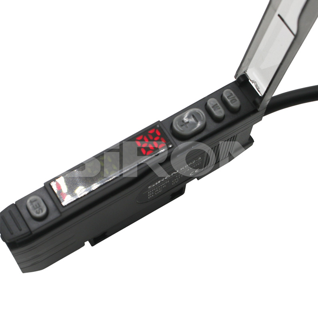
Display and usability matter deeply on the active factory floor. You need dual digital displays on the device face. One screen shows the programmed Target Value. The other shows Current Incident Light Level. Operators can perform rapid troubleshooting visually. They never need a digital multimeter to verify signals. Output protocols require careful upfront selection. Discrete outputs like NPN or PNP handle basic binary tasks well. Smart integration offers much more value. It enables predictive maintenance routines. It supports remote parameter cloning automatically. A modern fiber optic sensor amplifier integrates directly into plant networks seamlessly.
Analyze Contrast Ratios: Measure the light difference between the target and the background before selecting an amplifier resolution.
Calculate Required Speed: Determine your maximum parts-per-minute rate to set the correct response time mode.
Select the Output Protocol: Decide between standard discrete NPN/PNP wiring or advanced IO-Link communication networks.
Determine Hysteresis Needs: Ensure the device allows custom hysteresis tuning to prevent output chattering on vibrating targets.
Implementation realities often ruin perfect lab designs. Mutual interference remains a primary threat to reliability. We often gang-mount amplifiers closely together on standard DIN rails. Optical communication protocols prevent false triggering here. They synchronize emission pulses between adjacent units. Receivers ignore mismatched light signals entirely. Environmental degradation degrades performance slowly over months. Bent fiber cables cause severe internal light attenuation. Dust accumulation on lenses drops signal strength silently. Temperature drift alters electronic baselines over time. We must mitigate these physical risks proactively.
Alignment precision requires strict mechanical tolerances. In-fiber joining demands flawless optical interfaces. Beam alignment requires steady hands and immense patience. Mechanical mounting rigidity holds immense importance. It matters just as much as the internal amplifier software. Maintenance overhead presents another harsh reality check. Plastic optical fiber degrades naturally over millions of flex cycles. You need intelligent electronics to combat this. Automatic light intensity compensation prevents premature failure. It monitors LED degradation internally. It boosts driving current automatically. This keeps your calibrated thresholds stable much longer. A rugged industrial photoelectric amplifier handles these harsh factory realities effectively.
Always utilize side-by-side optical communication windows to eliminate mutual interference on DIN rails.
Install protective air-purge collars on fiber heads located in heavy dust environments.
Secure all fiber cables using dedicated mounting clips to prevent accidental sharp bends or crushing.
Enable automatic power control features to counteract gradual LED dimming and lens contamination.
Shortlisting logic requires a highly methodical engineering approach. Vendor ecosystem integration simplifies your control architecture significantly. Assess hardware compatibility alongside your existing PLC networks. Verify support for standardized sensor cables and M8/M12 connectors. Staying within known automation ecosystems reduces programming friction. It also minimizes your required spare parts inventory. Feature creep avoidance saves valuable engineering budget. You might see premium multi-color RGB light sources advertised. You might find complex internal timer functions listed. Do not pay for these software additions unnecessarily. Simple binary presence-detection rarely needs them. Focus entirely on high optical resolution and fast response instead.
Proof of Concept requirements demand rigorous field trials. Request a physical test unit before finalizing large orders. Test it strictly under worst-case plant floor conditions. Introduce heavy mechanical vibration to the mounting bracket. Expose the wiring to electrical noise from nearby VFDs. Blast the optical receiver under changing ambient lighting. Lab environments hide true operational flaws consistently. Only factory floor testing reveals real-world stability. Document every failure mode during this trial phase.
Performance Evaluation Chart | |||
|---|---|---|---|
Evaluation Metric | Standard Application Requirement | High-Precision Requirement | Risk if Ignored |
A/D Resolution | 12-bit (4,096 steps) | 16-bit (65,536 steps) | Inability to detect clear films |
Response Time | 250 µs to 1 ms | 16 µs (Ultra-high speed) | Skipped targets on fast belts |
Crosstalk Prevention | Up to 4 units | Up to 16 units via optical link | False triggering from adjacent sensors |
Maintenance Feature | Manual threshold adjustment | Automatic Power Control (APC) | Frequent line stops for recalibration |
A successful automation deployment balances multiple competing variables carefully. The best fiber optic amplifier fits your exact mechanical constraints. It aligns perfectly within your machine's strict spatial limits. It handles your target speed requirements reliably every shift. It matches your team's routine maintenance capabilities without causing frustration. We strongly encourage proactive engineering steps. Map your application's exact contrast ratio first. Define your maximum response time requirements accurately. Complete this baseline math before downloading countless manufacturer data sheets. Contact a technical sales engineer afterward. Use your mapped application data to demand a precise, factory-floor Proof of Concept trial.
A: Dust accumulation on external lenses reduces incoming light heavily. Internal LED degradation causes a natural drop in emission intensity. Ambient temperature fluctuations change the electronic baseline of the circuit. To prevent unexpected downtime, select units featuring Automatic Power Control. This feature continuously monitors light output. It automatically increases LED driving current to compensate for physical degradation and dust buildup over time.
A: We strongly advise against mixing different brands. Most standard units accept a 2.2mm pitch connection. However, internal optical tolerances vary wildly between manufacturers. Mismatched core alignments cause severe light attenuation at the insertion point. Proprietary clamping mechanisms might crush third-party cables. Always pair cables and amplifiers from the same manufacturer to guarantee maximum light transmission.
A: IO-Link enables continuous two-way digital communication. It unlocks remote teach-in capabilities directly from the main HMI. You can monitor sensor health conditions before failures actually occur. Parameter cloning represents its biggest advantage. When a sensor breaks, you install the new hardware. The PLC automatically pushes the exact previous parameters into the new device instantly.
A: Standard plastic fibers typically support an R25 (25mm) bend radius. Exceeding this limit destroys total internal reflection. Light escapes through the fiber cladding rapidly. This causes massive signal attenuation. Sharp bends also induce permanent micro-fractures inside the core material. High-flex models support tight R10 or even R2 radii safely. Always verify the manufacturer's mechanical specifications.


