
Please Choose Your Language
close
Choose Your Site
Global
Social Media
Views: 0 Author: Site Editor Publish Time: 2026-06-11 Origin: Site


Machine downtime drains manufacturing profitability every single minute. Unplanned stoppages require immediate, unambiguous visual alerts on the factory floor to ensure rapid intervention from operators. However, specifying inadequate indicator lights often leads to severe operational risks. Poor visibility, fluid ingress failures, and non-compliance regarding machine safety standards can easily turn a minor fault into a catastrophic bottleneck. You need a reliable framework to evaluate and implement these critical devices effectively. We built this guide as an objective, engineering-focused resource. It helps you shortlist the perfect led signal tower light for your automated machinery. You will learn how to navigate modular form factors, verify environmental survivability ratings, and guarantee electrical compatibility. This ensures you equip your facility for maximum uptime and uncompromising safety.
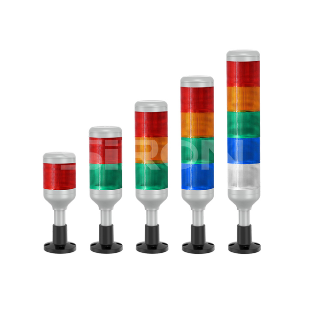
Modularity vs. Fixed: Choosing a modular signal tower light reduces long-term maintenance costs and allows for easy tier reconfiguration.
Environmental Survivability: Selecting the correct Ingress Protection (IP) rating (e.g., IP65 vs. IP69K) is non-negotiable for CNC or food-grade washdown environments.
Standardized Compliance: Adherence to IEC/EN 60204-1 color codes mitigates operator error and ensures regulatory safety compliance.
Integration Readiness: Modern stack lights must align with existing PLC architectures, requiring verification of NPN/PNP wiring or IO-Link compatibility.
Modern manufacturing floors move at a blistering pace. In these environments, operators cannot monitor every screen or control panel constantly. A reliable visual alerting system bridges this gap. It communicates urgent machine conditions instantly across vast distances.
Immediate visual and audible status indication directly reduces operator response times. When a machine faults or runs low on materials, every second counts. A well-placed machine status beacon cuts through ambient noise and visual clutter. Operators see a bright red or yellow signal immediately. They can walk straight to the affected equipment and resolve the issue. This rapid intervention prevents minor material shortages from cascading into extended line stoppages. It keeps production flowing smoothly.
Consistency drives safety. Implementing a uniform visual language across your plant floor minimizes cognitive load. Operators do not have to guess what a specific color means on different machines. A flashing red light on a CNC mill means the same thing as a flashing red light on a packaging line. This standard approach drastically reduces operational errors. When everyone understands the visual cues instantly, they make safer, faster decisions during high-pressure situations.
Engineers must choose between fixed, modular, and networked indicator architectures. Each category serves distinct operational needs. Choosing the wrong type often causes integration headaches later.
Many legacy machines use pre-assembled stack lights. Manufacturers build these units as a single, sealed piece. They arrive pre-wired and ready for installation.
Best for: Standardized OEM machinery. They work well when indication requirements remain completely predictable and unchanging over the machine's lifecycle.
Limitations: You cannot modify them easily. If a single LED module fails, you typically must replace the entire unit. If your operational needs change, you cannot simply snap on a new color or buzzer.
Modern automation demands flexibility. A modular signal tower light solves the rigid limitations of fixed units. They use separate color modules, bases, and acoustic components.
Best for: Dynamic environments. They excel where you might need scalable functionality. You can add buzzers or extra colors months after the initial installation.
Advantage: Twist-and-lock mechanisms dominate this category. They allow rapid, tool-free module replacement. You do not have to rewind cables or reprogram the base unit. You simply twist off the old module and lock the new one in place.
Advanced facilities now integrate smart indicators via industrial networks like IO-Link. These models move beyond basic digital on/off signals. They allow granular control of colors and flashing frequencies. You can change a single segment from red to blue dynamically via PLC software. They also collect operational data. You can monitor the temperature or runtime of the light itself, supporting predictive maintenance strategies.
Chart: Comparison of Indicator Architectures | |||
Category | Flexibility | Maintenance Complexity | Best Application Scenario |
|---|---|---|---|
Fixed / Pre-Assembled | Low | High (Full replacement needed) | Static OEM equipment |
Modular Systems | High | Low (Tool-free module swaps) | Scalable automation lines |
IO-Link / Networked | Maximum | Low (Software controlled) | Industry 4.0 / Smart factories |
Selecting an indicator involves more than just picking colors. You must evaluate physical survivability, optical clarity, and acoustic penetration. These dimensions ensure the device actually performs under harsh conditions.
The operating environment dictates the required housing protection. Fluids, dust, and chemicals destroy unprotected electronics rapidly.
IP54 (General Dust/Splash): Use this baseline for clean, dry assembly lines. It handles minor dust and light water splashes.
IP65/67 (Heavy Coolant/Dust): CNC machining centers require this level. It withstands heavy coolant spray, oil mist, and dense airborne particulate matter.
IP69K (High-Pressure Washdown): Food and beverage facilities demand IP69K. It survives high-temperature, high-pressure chemical washdowns daily.
Beyond water and dust, consider temperature extremes and chemical resistance. Polycarbonate lenses handle impacts well. However, you might need specialized glass or chemically resistant housings if your process involves harsh solvents.
An industrial warning light fails if operators cannot see it clearly from every angle.
Look for true 360-degree visibility. Lens design plays a massive role here. Prism cut lenses scatter the LED light evenly across the entire surface. Smooth lenses often create harsh hotspots.
You must also prevent ambient light interference. This phenomenon is called the "phantom light" effect. Direct factory sunlight can reflect inside an unlit lens. It makes the light appear illuminated when it is actually off. High-quality indicators use colored LEDs behind clear lenses or specialized internal reflectors to eliminate this dangerous optical illusion.
Visuals sometimes fail when operators face away from the machine. Acoustic integration provides a vital secondary alert layer.
Evaluate decibel (dB) ratings relative to ambient plant noise. A standard rule of thumb requires the alarm to sound 10 to 15 dB louder than maximum ambient noise. If your stamping press generates 85 dB, you need at least a 100 dB buzzer.
Compare your alarm tone options carefully. Continuous tones indicate steady errors. Pulsing tones usually signify urgent escalations. Multi-tone buzzers allow you to assign distinct sounds to specific faults. This helps operators identify the exact issue simply by listening.
You cannot assign colors arbitrarily. Random color assignments create confusion and violate international safety protocols. You must follow established norms.
Strict adherence to international machine safety standards is mandatory. The IEC/EN 60204-1 standard dictates how machines should use visual indicators. Following this standard ensures your stack light indicator complies with regulatory audits. It also guarantees visiting technicians understand your machine states instantly.
RED: Emergency or Hazardous condition. It demands immediate operator action. Examples include an emergency stop engaged or a critical safety guard open.
YELLOW/AMBER: Abnormal condition or Warning. It signals an impending issue. Intervention is needed soon. Examples include high temperature warnings or low material hoppers.
GREEN: Normal or Safe operation. The machine runs smoothly. No operator action is required.
BLUE: Mandatory action required. It signifies the machine needs input to proceed. Examples include prompting the operator to load a new part or scan a barcode.
WHITE/CLEAR: General information. You can use this for user-defined statuses. It often indicates a machine is powered on but idle.
State behavior matters just as much as color. Define clear rules for flashing states versus continuous illumination. Continuous lights typically represent steady-state conditions. The machine is running normally (solid green) or stopped safely (solid red). Flashing lights indicate urgent escalation. A flashing red light means an active hazard requires immediate attention. A flashing yellow light might mean the hopper is completely empty, whereas a solid yellow means it is merely getting low.
Great hardware fails if you install it poorly. You must plan the mechanical and electrical integration thoroughly before purchasing units.
Line-of-sight dictates mounting location. You have several options based on machine footprint.
Direct mounting places the light flat against the machine chassis. It works well for tall machines. Pole mounting elevates the light above obstructions. You can use standard vertical poles or L-brackets to extend the light off the side of a control cabinet. Wall mounting suits decentralized environments where the light sits away from the actual machine.
Address machine vibration aggressively. This is a severe risk factor. Stamping presses and large CNC mills shake violently. This vibration cracks standard plastic bases over time. We recommend specifying shock-absorbing rubber bases for any high-vibration application.
You must match the device to your power infrastructure. Specify your voltage requirements early. Most modern automation systems run on 24V DC. Facility-level indicators or older relay-logic machines might require 120V or 240V AC.
Clarify your control logic compatibility. Ensure your new lights match your existing PLCs. You will encounter two main types of DC control logic: NPN (sinking) and PNP (sourcing). If your PLC uses PNP sourcing outputs, your indicator must accept PNP inputs. Mixing them up causes immediate installation failures.
Legacy indicators use flying lead wire terminations. Technicians must strip and land five or six tiny wires into terminal blocks. This process takes time and introduces wiring errors. Highlight the benefits of M12 quick-disconnect cables. An M12 connector allows a technician to plug the light directly into an I/O block in seconds. It accelerates the installation process and completely eliminates crossed wires.
Selecting the right visual indicators protects your machinery and your personnel. It requires methodical evaluation rather than guesswork.
Define the environment: First, determine the exact IP rating required for your fluid and dust exposure.
Determine the tier count: Next, use IEC/EN 60204-1 compliance rules to decide how many colors you actually need.
Select the form factor: Choose between modular and fixed architectures based on your need for future flexibility.
Verify compatibility: Finally, confirm voltage and NPN/PNP logic matches your existing PLC hardware.
Your next steps should involve hands-on verification. Encourage your engineering teams to request product datasheets. Verify the electrical schematics directly against your PLC manuals. Most importantly, test a sample unit under the actual ambient lighting and noise conditions of your facility before executing a plant-wide rollout.
A: A stack light uses multiple colored tiers to communicate several distinct machine states sequentially (e.g., green for running, red for fault). A general industrial beacon is typically a single-status device. It uses one color to broadcast a specific, high-priority warning across a wide area.
A: Generally, no. Pre-assembled fixed units have sealed housings and hardwired internal connections. You cannot physically add new color tiers or swap a continuous buzzer for a pulsing one. You must purchase a modular system if you anticipate future upgrades.
A: As a standard rule of thumb, your buzzer must operate 10 to 15 decibels (dB) above the maximum ambient noise level of your facility. If your baseline factory noise reaches 80 dB, select a buzzer module rated for at least 90 to 95 dB.
A: The LEDs themselves are solid-state and require virtually zero maintenance compared to legacy incandescent bulbs. However, you must periodically wipe down the lenses to maintain optical clarity. You should also inspect the mounting bases and wiring integrity annually, especially in high-vibration applications.


